Keratron Scout Support
Wave Educational Videos & Documents
This page has been created to further your education and to give you more advanced concepts in Wave Fitting such as large diameter lenses and oval optic zones for Ortho-K.
Wave Lens General Topics
A proven method to consistently design large diameter contact lenses using Wave.
A Guide to Scleral Lens Fitting, Eef van der Worp, College of Optometry, Pacific University
A Guide to Scleral Lens Fitting, 1/1/2010
A Guide to Scleral Lens Fitting (2 ed.) Eef van der Worp, College of Optometry, Pacific University
Fitting Semi-Sclerals for a Long Term Post-RK Patient. (Dr. Henry Bumgardner)
Advanced Corneal Scleral Lens Design Philosophy, Jim Edwards, OD, Wave Software Designer
Scleral Lens Fit Scale
Michigan College of Optometry’s Vision Research Institute (VRI) announces the immediate availability the Scleral lens Fit Scale. This download-able item was created by the VRI for educational purposes and is designed to assist clinicians in practice.
The Scleral Lens Fit Scale demonstrates how to correctly estimate the clearance (amount of tears underneath portions of a lens, measured in microns) by comparing the tear layer thickness to the center thickness of the lens. Optic sections clearly demonstrate the tear thickness underneath the lens both centrally and at the limbal area along with images of various edge clearances.
Link to www.ferris.edu/ScleralLensFitScales to download and print or if you prefer to have a hard copy (8.5" x 11") card sent to you, please email CraigNorman@ferris.edu with the request and it will be sent to you immediately.
Click HERE for the SCLERAL LENS FIT SCALES copy.
Scleral Lens Fitting - Anatomy & Nomenclature
Click HERE for video about Scleral lens fitting as to the Central Optic Zone, the Limbal Transition Zone and the Scleral Landing Zone. The video is from the Bausch and Lomb Scleral Lens Fitting Series.
Scleral Lens Settling "Let's Settle This Once and For All"
The title of a poster by Adeline Bauer and Josh Lotoczky (Michigan College of Optometry) at GSLS was 'Let's Settle This Once and For All.' They found that scleral lenses completed about 25% of their overall settling within the first 20 minutes. All lenses showed at least 50% of their final settling by the one hour mark. After four hours, the lenses completed the majority of their settling. The average percentage of settling after four hours was 87.2%. Bray et al from the University of Waterloo (CA) presented the results of a pilot study on the changes in over-refraction after scleral lens settling. Based on OCT measurements, they concluded that scleral lens clearance diminishes over a 6-8 hour period after lens placement on the eye and that with this, a small change in over-refraction was noted, up to 0.25D in magnitude.
Creating Consistent Scleral Lens Edge and Limbal Clearance (Dr. David Sweeney)
This is a presentation on the Wave Contact Lens Designers Google page in which Dr. David Sweeney introduced his thoughts about "Creating Consistent Scleral Lens Edge and Limbal Clearance. What follows the video are the other members questions and thoughts.
Start of Discussion: Dr. David Sweeney:
Our Atlanta Wave Group has asked me about how I design Scleral lenses to get such a nice edge. I thought all the Wavers might be interested. Images of the edges are below.
My Wave design includes a Central clearance of 200um, 4-10D reverse curve on back surface, low deviation (less than 200um), aim for LA of 37.5-39.0 and aim for limbal clearance of 70-90um at HVID.
Key to this design is just enough limbal clearance with a gradual approach to the edge.
I was trying to close my talk by saying, while looking in box on lower left of design screen and clicking up or down a few times on the black ball, I like to end up with a thicker and straighter edge profile.
QA: Dr. Patrick Parks
Thank you for the video! Can you explain the protracted ~6cm extrapolation? How is that distance determined & how does it influence your edge design over 'conventional' limbal extrapolation? Thanks!
ANS: Dr. David Sweeney:
For extrapolation I pick a ring to start measurements. In the video I mentioned third ring. I meant to say the third red ring from the outer ring. Then, I pick a spot at 10:00 on conj outside the limbus and in my case I picked 6.5 cm from the third red ring. The first spot is set at a distance to spread out the rings but not too far out that you can't determine where to set the second and final third point. Ideally the third point might be just inside the window for ease of measurement. The second point was placed the same 6.5 cm distance from the third red ring at about 7-8:00. The final point is set at 9:00 at same horizontal distance from center as outer extrapolation ring at 3:00. You want to end up with the outer rings evenly spaced.
QA: Dr. Paul Levine:
David, you working in a type of oblate design with that reverse curve?
ANS: Dr. David Sweeney:
I learned from other manufacturers that the reverse curve starting at the edge of the optic zone worked well to center the lens on the eye, just clear the limbus, and create a nice edge. With Wave there is so much more you can do with Sclerals such as multifocals. front toric, toric peripheral curves in GSym and FF and even all of these in the same lens.
QA: Dr Graham Rasanen:
I think it would be extremely helpful to once more review why you pay attention to lift and not edge angle.
I have noticed that in the wave fit set a 41 edge on 44bc != 41 edge on a 46 BC
the edge angle is relative to BC, not uniform across the lenses ... correct?
so is the lift angle a uniform measure by which to say a 41 is a 41 no matter what BC you have?
ANS: Dr. David Sweeney:
Key to extrapolation is consistency and measuring with ruler on your computer monitor the same way for every topography you are using. That might mean going back and re-extrapolating.
QA: Dr. Graham Rasanen:
So I had a change to sit down and play with this concept. I see how it changes the landing approach.
But Irregular/ectactic Ks seem to create decent apex clearance then spikes up to 50-100u outside while going toward the limbus. These eyes have very steep BC due to wave trying to match the shape
Do you abandon the reverse curve concept on those corneas? I can create a more even TLT and something that approaches what you made if I shrink the red ball placement to ~6mm, and steepen it, eliminating the RC altogether.
Curious if you have PKP example ... that's the ultimate challenge.
In the picture below left wave screen is Sweeney's method as described in this thread right is the "usual method" with the curl periphery... i do not like the clearance on the left.
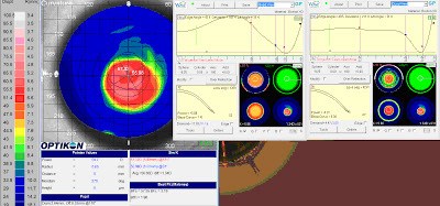
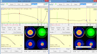
Here's my "fix" to my message previous to this. had to flatten the BC rapidly to produce a more normal tear pattern while still keeping the Sweeney approach
ANS: Dr. David Sweeney:
To answer why LA is more important than EA, check out this link for Richard Anderson's beautifully illustrated schematic: http://training.eyequip.com/assets/lens-edge-angle-schematics.jpg
The LA measurement starts halfway between 11.5mm and the edge of the lens. So, if you are making a 15.5mm Scleral lens the LA starts at 13.5mm - the point where the lens touches down on the conj/sclera. You can also see how Deviation is calculated. Having a low deviation has a more gradual approach to the landing area and flatter rather than rounded back side of the edge.
Unfortunately, I do not use the trial lens set because my limbal clearance and edge design is different.
My design approach works fantastically well on keratoconus patients. I recently refit a keratoconus patient that was very comfortable in another manufacturers Scleral lens but became presbyopic. With Wave I designed a Scleral Multifocal lens with center near add OU. He and I were amazed at how crisp and clear his vision is far and near in each eye. The comfort was also much better than his previous lens. His previous lens had a very nice central clearance, limbal clearance and landing/alignment on his conj/sclera. I think it was because I could create a nicer tapered edge with Wave.
I am not to concerned about the rise in the midperiphery as that is usually where the steepest part of the cone is located. I can't remember ever moving the red ball in closer than 9.5mm. In your case, to make the fluorescein view look prettier, try moving the red dot out to 10.5 and hitting current settings and create the design again. My first lens on all Wave lenses is always a trial lens because with normal and irregular corneas, there is so much going on that you get close with the first lens on central and limbal clearance and edge landing profile as well as Rx. Then you can nail the fit and Rx on the second lens and it doesn't cost as much. I let my patients know that it usually takes 2-3 lenses to optimize fit, comfort and vision.
I believe we need some blue near the peripheral cornea on the topography and that might be difficult fitting a Wave lens for patients with PKP. I work with another manufacturer for those patients that I can't get a reliable or usable topography for wave designing.
Other Comments: Dr. Phil Stockstad:
I also dabbled with this approach. On a regular cornea that was extrapolated beyond the limbus I designed a lens that gave 200 u of central clearance and matched all fitting targets. On the same cornea extrapolated to the limbus I designed theexact lens with the same placements and sags for all 'balls'. The exact same lens showed 371 u central clearance with an additional 100 u of limbal clearance over the 'extra' extrapolated lens.
For PKP corneas the only way I have found to get a flat edge with adequate limbal and peripheral clearance is to design the flat edge and cut into the lens with a 8.5 mm tool.
Here are the steps:
- Change to 8x and 560um settings. Use RSym, click the Edge box (to get FF edge) and keep center thickness between 35-42 (thicker center with higher cyl or more irregular corneas to prevent flexing; thinner center if you add prism and for regular corneas) and Edge thickness at 26-30. (If I am creating a multifocal near zone, I add -0.50D to the Over Refraction box and change the Add in Rx to (glasses Add +1.00D). Then, I start by setting dots R,B,P at 9.5-10.5 mm (HVID - 1.5mm), HVID + 0.40, HVID + 1.40, and diameter HVID +4 mm. Go to Tools Box and let it fly on Current Settings and save. Then reopen design, raise black ball a few times, then bring pink ball down a few times and continue this until I get INTERMEDIATE settings of around 120um central clearance and 41 LA.
- Now it's time to create a 6-10D reverse curve on the back surface. Click down on blue dot (while still at 8x) to create a 6-10D reverse curve that aids in centration and helps keep the deviation down to get optimal edge. You may need to switch to 1x and click on red/blue dots to get the amount of Reverse you want. Then I go back to the pink and black ball to get FINAL 200 central clearance and 37-39 LA. LA determined by flat K (flatter K go towards 37) and HVID (smaller HVID go towards 37).
- Then I put cursor at HVID and check the LIMBAL clearance - aim for 70-100 (less clearance flatter K's and flatter peripheral corneas). To lower LIMBAL clearance I click down blue 1-4 times. To maintain Reverse Geometry on back side you will also need to adjust red dot (Base curve). For example, to reduce LIMBAL clearance, go down on blue 1x, then go down on red 1x. Then adjust pink up 2x and black down at 4x to get back to 200um FINAL central clearance and LA you want.
- To lower the deviation even more, try changing edge thickness between 26 to 30.. Also, try to make LA as high as possible (or err on higher side) as this will bring deviation down and make a better aligned edge to the conj/sclera. LA is determined by looking at K's and peripheral corneal curvature.
- Overplussing by +1.00, then -050 to the distance. Is this the same on dom and nondom? Yes. Since, I add +1.00 D to the Add, I usually add -0.50D to the Over-refraction Box. The Add and -0.50 just seems to work out better on normal corneas although your never sure what the over-refraction will be with irregular corneas - I usually order a trial lens designed as if I was ordering for the patient to wear as cost is less. I like to put the Red dot on front surface based on the spread sheet attached. You may want to go with 0.1 smaller add diameter with dominant eye and also lower add power on dominant eye.
I have a hyperope right now complaining of blur in the distance AND near but OK intermediate. 3.5pupil, +100 dist +150 Add. I used 2.5N and used spec Rx as written. Haven't yet done the follow up to re-check complaint. See above answer for things to try next.
If digging in along horizontal and edge lift in vertical, go to 560um setting and check Modify button (still in RSym mode design but GSym modification) and change to 50% setting. Then I click up 8x on the pink in the horizontal and down on the pink in the vertical to raise pink dot at least 60um-100um higher and to keep central clearance about the same it that was OK with first lens. Then with black dot, and at 8x click on horizontal and vertical (still in 50% mode) to make the LA same or possibly 0.5 to 1.0 flatter (less in value) along horizontal.
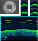
OCT helps to check alignment in horizontal and vertical conj / sclera as well as central and limbal clearance.
Scleral Lenses Boston Gas Permeable Lens Material Fitting Videos
GP lenses come in a variety of diameters to best meet the needs of fitters and patients. To meet the demanding needs of specialty fitters and the larger sizes or scleral lenses, Boston materials buttons are manufactured in a variety of large diameters in XO, XO2 and Equalens II.
Click HERE to navigate to the Scleral Lenses Boston Gas Permeable Lens Material Fitting Videos
Semi Scleral Design, David Sweeney, OD (2016)
Keratoconus & Transplant Designs, David Sweeney, OD (2016)
Wave Scleral Lens Designs with Pentacam CSP Software (2019)
Wave Scleral Lens Designs with Pentacam CSP Software
What are some pearls on scleral lens designs with the CSP software or advice on where to look for info in getting started using the CSP and the Wave Contact Lens software?
1. Learn how to acquire clean scleral data with the Pentacam. Having two people available is helpful, one driving the Pentacam and the other manipulating lids as necessary. Get some of the new rubber lid manipulation tools from Oculus. Of the five images the two most difficult are usually nasal and superior. For the nasal scan, its help to have the patient tilt his/her head nasally which exposes more nasal sclera. For the superior scan, it is sometimes necessary to have the patient leave a gap between their forehead and the headrest. Some eyes are just too sunken in to get enough data and you do what you can and rely on extrapolation.
2. HVID is important and sometimes there is disagreement between the Pentacam and Scout. I trust the Scout measurement the most. If Wave crashes during the design process, try increasing the initial vault or decreasing diameter initially. You'll have to go back and fix things, but at least you'll be able to get going. Pay attention to the width of the landing zone. You'll want about 1.75mm of contact when the lens lands. This translates into most lenses needing to be 16.5mm, the max currently allowed in Wave, unless the HVID is unusually small.
3. The default front surface optic zone is 8mm. I change this to 9mm in most designs, unless the lens is highish plus.
4. Ditch the default prism ballast. It is almost always unhelpful and serves to thicken the lens considerably.
Scleral Lenses
Orthokeratology Scoop by Antonio Calossi
Great Information about clinical techniques in Orthokeratology. Click HERE .
Advanced Orthokeratology - Oval Optic Zones
Myopia Control - Today and Tomorrow
Another fundamentals course at GSLS focused on 'Building the Myopia Control Practice,' by Marco van Beusekom ('Working with Kids and Parents in the CL Practice'), Ron Beerten ('Using Technology to Increase Success in Orthokeratology for Myopia Control') and Thomas Aller ('Soft Lenses for Myopia Control Today and Tomorrow').
A number of handouts are download-able via the link below. In the general session 'The Future of Myopia Management with Contact Lenses,' the discussion was moderated by Brien Holden (Where to from here - Possibilities and Probabilities). Earl Smith (What's new in understanding of myopia induction?), Monica Jong (Who is at risk and what are the consequences of high myopia?) and Thomas Aller (Myopia control - my way) completed the session. A Free Paper presentation by Zhi Chen showed that relative peripheral corneal power change in myopic orthokeratology is negatively correlated to two-year axial length growth in children.
Chad Rosen looked at 'Do Asian and Caucasian Eyes Respond the Same With Overnight Corneal Reshaping?' They did find a difference in mean spherical equivalent between Asians & Caucasians when incorporating starting age groups.
Bruce Morgan et al looked at the use of OCT imaging of corneal reshaping lenses and concluded that the system they used was capable of measuring the very small micron changes seen in the post lens tear film and corneal epithelium of corneal reshaping lenses. The Michigan College of Optometry (US) also introduced a very informative websitemyopiacontrol.org.
Ortho-K Design Considerations (VBD Wave Boot Camp 2015), Jim Edwards
Jim Edwards presents to us his thoughts to consider when designing a Wave Ortho-K lens. He is using the Wave version 8.10. This video was created April 2015.
Large Lens OrthoK Design Perspective (2015)
Click HERE to read the the large Lens OrthoK Design Perspective.
High Myope With Flat K's (2016)
Click HERE to read the High Myope With Flat K's document.
Myopia Control Strategy (2016)
Click HERE to read the Myopia Control Strategy
Getting Hyped About Hyperopic OrthoK (Gavin Cohen, OD) 2016
Click HERE to view the power point. There is no sound.
Paragon CRT Refit With Wave NightLens (David Sweeney, OD) 2016
Orthokeratology for Hperopia and Presbyopia (Bruce T. Williams, OD, FIAO) 2016
Click HERE to learn what modifications are needed to design orthokeratology lenses for hyperopia and presbyopia.
How Does OrthoK Work ? (Dr. Jeff Jeruss) 2017
High Myopia with progression (David Sweeney, OD) 2017
Click HERE for a slide presentation.
Multifocal OrthoK 2018
Q: I want to design corneal (or scleral) multifocal Ortho-k for one hyperopic and one myopic patient and would like to try to get better near without sacrificing distance. Has anyone had success with this? If so, could you provide tips?
A1:
Although I have not had as much experience fitting Multifocal Ortho-K as many others and do not consider myself an expert in this area, I can give you some pointers to get you started.
Firstly, before you embark on multifocal Ortho-k, you should have mastered single vision Ortho-k for adults and be able to trouble shoot for lens decentration, or better yet, have a record of no decentration remakes. Secondly, start with low astigmatism and moderate myopia/hyperopia/presbyopia. Make sure you have a good candidate (highly motivated, be able to come in for frequent follow-ups, no dry eyes, no huge/tiny pupils).
As for design principles, for myopic multifocals, understand that all Ortho-k lenses are already a center-distant/surround-near fit. The higher your Rx, the higher your para-foveal add you get. So, you can just start with a standard design with a conservative power demand (e.g. a 6.2 OZD, +1.00 to +1.25 lens power in dominant eye and +0.50 to +0.75 in non-dominant eye) and see what you get. If this doesn't give you enough effective add, do the following: change S-shape to +0.20, decrease OZD, or decrease Target Power, keeping in mind that night glare may worsen.
As for Hyperopic-MF, there are a lot more factors to consider, and I would probably do you wrong by giving you a simple algorithm.
A2:
What I keep trying to figure out is if docs are doing true multifocal Ortho-k, where we are not sacrificing distance to get near (or barely sacrificing). It sounds like what you are doing is what I am doing, but when I get a mid-presbyope, I am definitely sacrificing distance in the Non-dom eye. If you have a patient with a +1.75 add, what is their distance VA and near VA typically?
Tight OrthoK Periphery 2018
Q: I have a 12-year-old OrthoK patient who is a week out and is doing well. There are no reports of difficulty when removing lenses; however, when prompted, she does say they sometimes they make a popping noise during removal. Pt came in for a follow-up this morning. I took a brief look at topos, which were of poor quality (missing peripheral data). Pt. was 20/20 OD and 20/60 OS (sc). Slit lamp showed mid peripheral "furrowing" OD, OS. She had a very distinct ring staining pattern corresponding to the edge of the retainers. Retainers in situ reveal very little movement with blink and inadequate (non-existent) edge lift. She has a large arcuate return zone bubble OS.
I am thinking I need to loosen the periphery by clicking up on the intermediate curve (blue ball). However, when I do so, it drops the apical clearance to 0 microns. Should I just adjust the pink and black ball to increase edge lift?
A1:
Remember that wave displays are theoretical. Clicking up on blue to loosen the fit/decrease the sag sounds like a good approach. The zero central clearance will likely not be zero, just like the 20 or 30 micron clearance in the alignment zone after clicking up on blue will not be 20 or 30 in real life. Use the display as a guide and your nafl pattern as your direction to make changes.
A2:
I suggest decreasing the OZ to 5.6, loosen the inner alignment zone by clicking up on the blue ball 8-10 microns, loosen the outer alignment curve by clicking up on the pink ball another 6 microns, and raise the edge lift by clicking up on the black ball an additional 6 or so microns.
A3:
I'm surprised that you didn't find undertreatment (residual myopia). A2 is on target, but I do not believe it will be enough. Your lens has entirely too much sag in the periphery as evidenced by your treatment maps. You will also ultimately need to click up on the red ball as well – your reference maps are totally overestimating corneal sag, hence your problem is here.
Wave Hyperopic OrthoK with Astigmatism Correction (David Sweeney, OD) 2018
Hey Wavers,
I notice some discussion about Wave Hyperopic OK and Astigmatism on the Wave Google Group.
I had a little extra time last weekend to create a PowerPoint Case presentation .
Please take a look at this slide video (thanks Vance) to show my notes.
In 2012 my 53yo female computer trainer wanted to be free of glasses for near.
Rx OD +0.25 - 0.75 x 95 and OS plano - 0.50 x 70 with +1.75 Add. She had slight ATR corneal astigmatism with K's of 44.19D @176 and 44.33D @ 86. HVID was 12.2 and Pupil sized was 3.70mm averaging 4 OD topography maps. She was OD dominant but had better uncorrected VA OS so we started her wearing a HOK Wave lens with spherical base curve with round treatment zone in her right eye only for intermediate/near vision. Her left eye was left uncorrected for distance vision.
Unfortunately, a year ago while wearing her 2015 HOK lens design, refraction was OD -1.00 - 1.50 x 90 with VA at near 20/40 and near reading range 8-16". To improve near VA and near range to see her computer better we created a HOK Astigmatism correcting lens design with toric base curve with oval treatment zone with reduced overall power. She has been very delighted to see more clearly with improved near range to see her computer and read without glasses.
OrthoK and RK, Julio Arroyo, OD 2018
Quite often, we get an Ortho-k consult patient in our chair (I am sure you do too) s/p RK (radial keratotomy). The least fortunate ones have very unstable vision with glasses, and their refractive status varies at different times of the day. Many of them were and still are or have become post-surgically hyperopes with different degrees of astigmatism.
Over the years, I have attempted Ortho-k on a few of these individuals, many times to only find frustration for the patient and myself. The corneal structure instability and the post-surgical warpage make it a real challenge to mold these folks effectively. Lately, however, I believe I have seen interesting results worth sharing.
The patient mentioned here was thoroughly advised about the complexity of the case and prepared for realistic expectations. In these cases, I usually keep bifocal semisclerals in the back burner as the B plan, should plan A fail. Again, patient is inform-consented and signed accordingly.
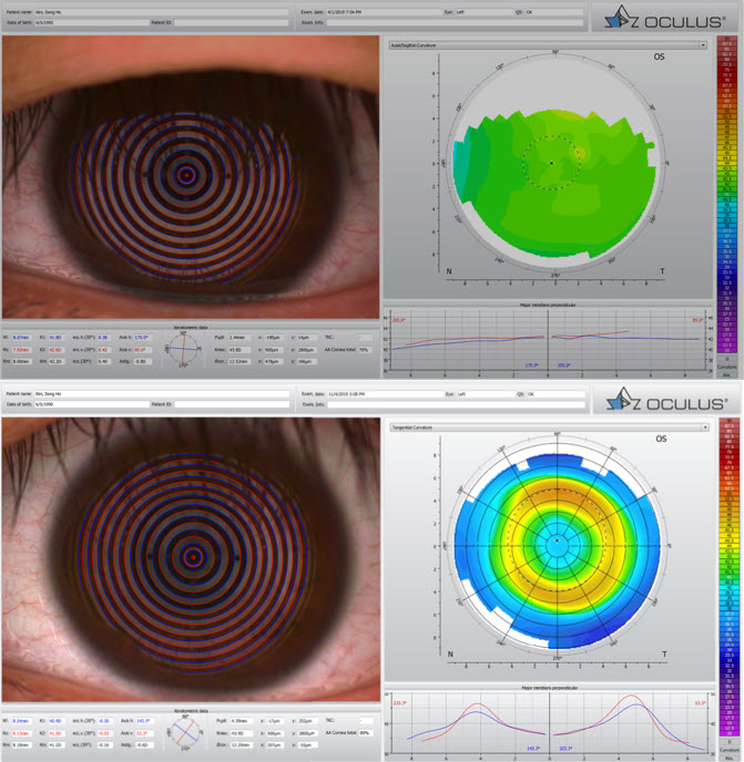
I have attached the pre- and post-molding maps.
A few things I have learned about these fits and mold design are as follows:
1. Small treatment zones (TZ/OZ): Whereas larger TZ/OZs tend to work well on regular healthy and post-lasik corneas, I find a smaller TZ particularly preferred in these post-RKs.
2. Land on the valley: The landing zone (LZ), or what I like to call the elbow, works better if placed right before the cornea transitions into the steeper paracentral area, or the valley before the hill.
3. Size does matter: Inevitably, if there is a time for a corneo-scleral (translimbal) design, this is it. As a side note, even though regular sized corneal molds may work well in H-OK, corneo-sclerals are so much better at moving tissue that 99% of all designs I do for H-OK are in fact larger than K.
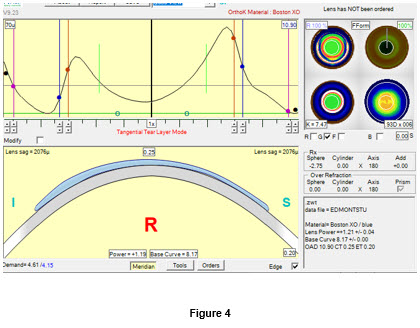
4. Camel better than dromedary: The attached image of the wave design post-curve profile (Figure 4) shows the double hump. Creating that secondary chamber in between the landing first reverse curve and the peripheral curve seems to help stabilize the mold and the hydrodynamic forces involved in tissue/fluids migration.
5. Aim high!: Whatever refractive demand you need to mold, make sure to aim twice as high, as it is more than likely that you will fall short otherwise (and anyway). So, for a +2.00, design as if it were a +4.00 at the least.
6. 3rd one lucky: Get ready to have to design more than 3 molds to get it right.
And last…
7. If you can think of a time to use Free-Form design, this is it!
So, if you are trying to find a new wave of excitement in Ortho-k, you got it!
Large Diameter HOK (Toprak design) Case Summary (David Sweeney, OD) 2020
OrthoK
Design A Custom Wave Contact Lens In 7 Simple Steps.
Information on the Correct Way to Extrapolate Patient Data.
The Wave Contact Lens System, Auto Design Custom Settings feature also known as Configuration Settings.
Detailed Discussions On The Correct Way To Add An Over-Refraction.
Wave Trial Lenses, Jim Edwards
Correcting Lens Rotation, Jim Edwards
Adjusting The Alignment Zone (2016)
To tighten or loosen the Wave Contact Lens alignment zone you will need to make the adjustments in the Tear Film screen in the Wave software program.
To tighten the adjustment zone click down on the Intermediate Zone adjustment point (blue ball).
To loosen the adjustment zone click up on the Intermediate Zone adjustment point (blue ball).
Myopia Control Facts / Children (2016)
Here are a couple of papers that address the increased frequency of Myopia. One addresses Myopia on a world wide scale and the other paper is specific toward children.
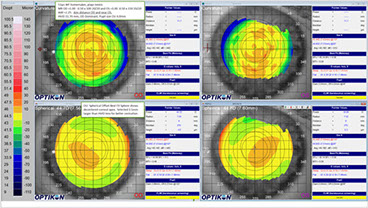
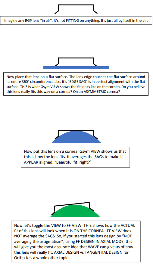
Different Tear Film Pattern View - Quad View vs. Flourescein View (Real Reason) (2017)
Has anyone ever compared the Flourescein pattern of your design in quad form (where it shows the 4 pictures: anterior, posterior, fluorescein and cornea) versus just the fluorescein form? I occasionally see that they are significantly different. Which one should I trust?
Click HERE on a short video about the ability to toggle between using FForm or GSYM corneal data for Flourescein and Tear Layer graph.
The real reason to have the ability to toggle tear layer graph views.
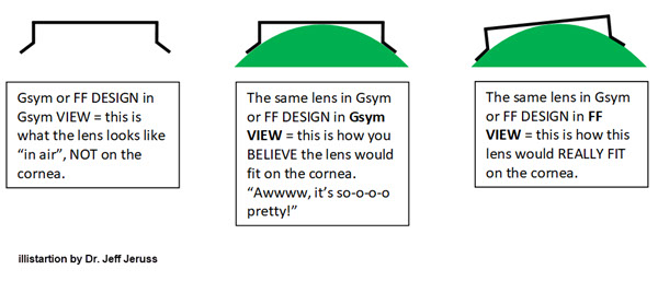
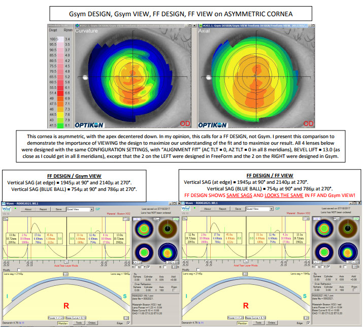
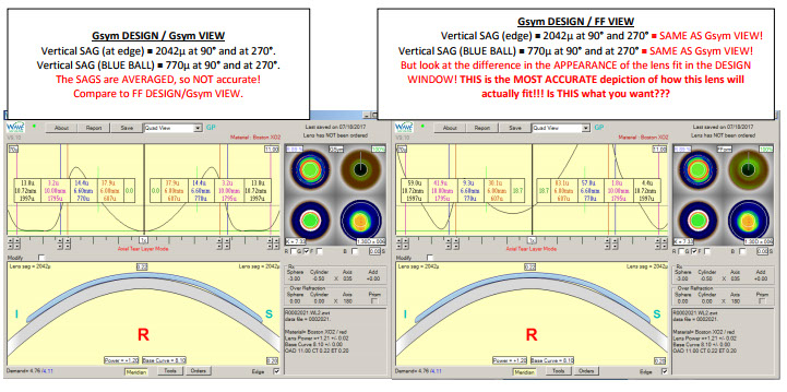
Viewing The Wave Design to Maximize Understanding Fit and Results (Dr. Jeff Jeruss) (2017)
Wave Software "S" (Shape Factor) Tool (2019)
Q: Can you please what the “S” factor is and when to use it.
A: Shape factor makes the base curve of the lens aspheric, i.e., steeper than initially intended then flattening out more quickly or vice versa. You can see this by activating the back curvature view of the Wave window (lower left of the quad display) wherein the base curve is no longer represented by a straight line. It will either show a line that dips (flattens) toward the center of the lens or lifts (steepens) at the center of the lens. If you uncheck the “B” box, the effect is much more noticeable because instead of a gradual change across the base curve, you practically get 2 distinct curves within that zone of the lens. When the “B” box is unchecked, you can also use the nodes (green naught symbols) to adjust where the “step” within the base curve occurs.
An aspheric BC that is flatter centrally is generally used for myopic ortho-k to create a slightly larger treatment zone or to help smooth out central irregularities. The opposite is generally used to accentuate hyperopic molding.
Shape factor can also be used to create a lens with a very customized back surface to match an irregular cornea or to create a thicker tear layer underneath the reverse curve of a myopic ortho-k lens with the intent of creating more plus power and myopic defocus.
There are pros and cons to using shape factor in most scenarios. Perhaps others can chime in with their experiences. In my office where I predominantly see myopic kids, i do not use shape factor very often.
Wave Screen - Using Aspheric S With Unchecked "B" (2019)
Q1: Does anyone ever use the Checked B box with S = +0.2 to get the widest possible OZD? I am trying to get the widest treatment zone possible for an adult Ortho-k where optimum night vision is preferred. No matter how wide the OZD and RC diameter are set, Wave will blend out the true power OZD to a similar size or less (the flat line on the back curve map). The only way to increase it beyond the 4.3 mm is to use the checked B box.
Please see attached two designs, one with a typical blended myopic Ortho-k design (B box unchecked, S shape at "0"; this gives a constant Base curve out to about 4.3 mm), and one with S = +0.2 and B box checked, which increased the flat base curve out to 5.1 mm, as wide as I can get. This example is for a typical low myope with standard 44.5D flat K, BTW.
If you do use this type of design, did it increase the treatment zone? How did it affect comfort? Did you get SPK in the peripheral cornea (at the blue dot or the pink dot junctions)? Did your patients see any improvement in night vision? Any comments on differences in outcome of unchecked B and checked B would be appreciated.
[EDITED] I decided to order one lens B checked and one not for the patient. I used the larger OZD for the checked B box to get the wider treatment zone because using a larger OZD for the unchecked B won't let me increase the treatment zone.
A1:
You don't need to do S = +0.2 to get a larger diameter 'flat zone' - simply ticking the B box increases the OZ zone already when keeping S = 0. I ran a simulation on a 44.50 cornea -3.00 and "without B", tx zone was about 4.4, and with B ticked, it was 4.8. You got it a little wider because you made your OZ bigger by moving the red ball out. Specifically, the 'S' factor does not flatten part of the OZ bigger.
I haven't compared the two fitting methodologies. I always tick B, even with myopia management. I just make the OZ a fraction smaller, say 5.8 or 6.0, for young myopes. This works well, and most of my young myopes stop progressing completely.
With regards to flare / halos at night, I fitted myself (-5.00 with 2.00DC WTR), one with eye B checked and one without. I must add, I have anisocoria, so my right pupil is about 1-mm bigger than the left. I definitely get more halos on the right. I didn't notice a big difference in the overall treatment zone between the two modalities.

Wave Screen - Quad View - FForm vs GSym view (2019)
Q1: In the WAVE screen, in the upper right corner with the Quad view, the view for FForm vs GSym is confusing. If I'm doing a FF design, I know I look at the FForm view. This time, topos look like they’re made for GSym. When I look at the GSym view, it looks all nice and pretty - just the way I'd like it to fit. In FForm view, it doesn't look bad, but definitely a little funkier. What are the pros and cons of each view and why are they different?
A1:
The only way we should “view” (the most accurate view) is in “FF view.” Don’t ever set it to Gsym view.
A2:
Figure 1 shows the post-lasik HOk, Gsym, pre and post molding. Notice the Wave expected asymmetry and the great molding outcome.
A3:
The post-treatment map shows approximately 0.8 mm temporal decentration of the treatment zone. I would consider that to be excessive if this were a myope, and I would absolutely go with a FF design to improve centration. In your HOK case, the design window shows a loose superior meridian alignment zone (starting with > 25 microns of TLT at the RED ball and finally touching the peripheral cornea at 10 mm). That makes me wonder how loose the lens is in the temporal meridian because perhaps that is what causes the lens to decenter so much temporally. I hardly ever see hyperopes in my practice, so my experience with HOK is nowhere near yours. But, wouldn’t a FF design be called for here? I have heard and read how forgiving hyperopic Ortho-k patients are, so I’m guessing that 0.8 mm of treatment zone decentration is something that they might not complain about. Do you think my assessment is accurate?
A4:
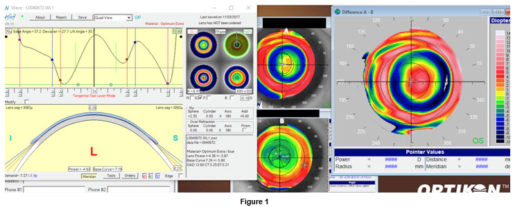
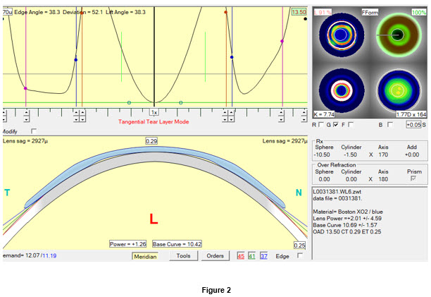
I like your 'in theory' fitting reasoning, it makes sense. However, for a long stretch of time, I designed every one of my cases in FF; the boldest conclusive yield was that I couldn’t notice a difference besides the time wasted in a longer design process. I agree there is some decentration in the map in Fig. 1, but I bet that FF would not change that. I have already proven it many times. In Figures 2-4, the quick maps could perfectly apply to myopic Ortho-k as well. The well-centered Ortho-k treated kmap with a gsym design shows poor landing alignment, yet it works.
Also, hyperopes presbyopes are the most unforgiving patients in your chair, not the opposite. You mold their corneas, do a post ttx MR, and everything matches well. However, often enough, they are frustrated and unhappy no matter how centered your treatment zone is. I say, hyperopic molding induces even more higher order aberrations than M-ok. Plus, kappa angle is unique to the individual.
To add:
1. Ideally, we want to mold the visual axis. But in reality, we just try to mold a cornea. If getting a centered post-molding map is managed but the kappa angle is high (diff between visual axis and pupillary axis), your treatment zone will be decentered from the visual axis. IMO, it becomes extremely complex and unpredictable to troubleshoot this problem, even with the Wave tool for decentered OZ/TZ.
2. What I have noticed over the years is that there are always small variations in centration from one day to the next.
Q2: Do you ever use FF these days, and if so, what's your criteria? On a case like the one below, do you just let WAVE do its thing and not really worry about how it looks on the initial design screen and then make adjustments as necessary based on VA/refr, maps, and on-eye fit? Also, I noticed that this one and the H-OK design you showed are both corneo-scleral. Do you use those a lot, or is it mostly for H-OK and the fact that the one below is such a high myope?
Lastly, is there a particular reason that you design (exclusively) in Tangential vs Axial mode? I've begun using composite maps (Medmont) for my WAVE export and find that WAVE designs these lenses with more sag than if I use just a central map. When I design in Tangential, this cuts the total sag by about 15 vs Axial and seems to work pretty well. What’s your rationale for Tangential?
A1 (to Q2):
1. FF is an exception to the rule, not the norm. If you have persistent decentration, I may consider FF. Although, most times, going CSM is usually the most effective and predictable fix for centration problems.
2. I don’t let WAVE do its thing solely - there are usually a few adjustments to be made after WAVE processes the initial design.
3. I use CSM in H-Ortho-k virtually every time. CSM is also, again, a great fix with centration issues, comfort issues. I will also consider CSM every time results are substandard with non-translimbal designs.
4. Tangential vs. Axial:
- I design Tangential with ALL CSM and with corneal toric myopic designs.
- I design Axial with corneal myopic (non-toric) designs.
A2:
You can use whatever design mode, lens size, shape, etc. that you want, and you can let WAVE calculate the lens for you without adding any additional touches to it. The odds are very good that you'll have a successful result, although it does depend somewhat on your definition of "successful result."
I tried out Gsym mode and even used the Modify box to make the periphery FF. I found THIS to be MORE time consuming than to just start out with FF. An important advantage of starting the design in FF is that if you start out "maximizing the fit" as much as possible (which is what FF lets us do), then if you DO need to troubleshoot the result, you'll know that you've ALREADY maximized the fit. Then, you can start loosening, tightening, etc. without having to wonder if maybe Gsym was causing the problem and then having to order a 2nd lens in FF - a 2nd lens that COULD HAVE BEEN your FIRST lens had you used FF.
I feel somewhat uncomfortable designing CSOK because of the extra lens mass causing SPK more often than I'd like to see. Also, since I don't have a topographer that measures the sclera, whenever I design a lens that is larger than the cornea (whether CSOK or scleral), I am GUESSING more about how to land the thing on the sclera than I would be with a corneal lens. If I didn't have the ability to do anterior seg OCT, I think it would be more risky and somewhat unprofessional to fit larger-than-cornea lenses.
There are plenty of ways to improve corneal lens centration without having to resort to CSOK. One of them happens to design in Axial mode because this creates a tighter alignment zone than Tangential (by approximately 7-12 microns). Although, it is no big deal to tighten the alignment zone in Tangential mode so that the SAG is EXACTLY IDENTICAL to that produced using Axial mode. See for yourself by playing around with the WAVE simulation tool. Using the exact same parameters, design a lens in Axial, then a second one in Tangential, then play with the balls to make the Axial lens look EXACTLY like the Tangential lens...or vice versa.
Since we are trying to do Ortho-k to maximize the refractive result on the visual axis (not the corneal axis), it makes sense to use Axial mode to design. If I have a cornea with especially high eccentricity, I'll need a flatter alignment curve so I'll often just design these in Tangential (vs Axial then loosen the periphery "by hand," which is more time consuming).
A3:
1. FF is the exception for corneal Ortho-k lenses. I use FF for every scleral lens that I design using the Pentacam CSP software. But for corneal Ortho-k lenses, GSym still reigns supreme.
2. GSym (and even RSym) is virtually every corneal Ortho-k case I do and often it is the first lens that is successful.
3. I never let "WAVE do its thing."
4. CSM is truly a rarity for me. It adds risk and liability, and proper treatment can be accomplished well with corneal lenses for myopes/hyperopes/multifocal myopes/multifocal hyperopes/ and those groups even with some fairly high cylinder (4-5D).
5. I design in Axial only for everything.
6. I agree with using ONLY the FForm display. The GSym display massages data (lies to me), and I want to see exactly what I am dealing with.
7. Regarding troubleshooting a result that was achieved with a GSym lens and then finding out that a FForm lens was needed, I offer this perspective. Spend more time analyzing your source topography BEFORE you start the case so that you don't have a "treatment surprise." You SHOULD know before ever getting the first lens designed/manufactured/on eye/back for follow up how the case is going to go and predict whether or not you are going to have some problems/issues. If you spend the time developing these skills, you will know before you start the case what some of the troublesome areas might be. Then you can design for them before they even become an issue.
Difficult Internal Astigmatism (2019)
Q1: I have a patient who has been in Ortho-k a few months and have not been able to reduce his residual astigmatism in his left eye. I attached the original and last topo. Rx to start was -3.00-0.75 x 90. Now, it is plano -1.25 x 90. I have already tried relieving the treatment in the 90 degree axis, which helped but only to a degree.
Would designing an oval optical zone with more demand in the 180 axis and reducing the overall target power help?
A1:
This patient has 0.80 D WTR Kcyl and 0.75 D ATR Refractive cyl, so you should expect significant residual ATR cyl post-treatment. Don't design an oval optical zone. Loosen the alignment curve in the 90 and 270 axes, so there's less suction there. That should help maintain the cornea's WTR toricity some.